Overview
The article underscores the critical importance of mastering phase angles in electrical engineering, particularly for enhancing circuit analysis and measurement. Understanding phase angles is essential for optimizing efficiency in AC systems, and this knowledge is pivotal for addressing challenges such as signal distortion and noise interference. Furthermore, the article highlights the necessity of accurate measurement techniques, which are vital for improving performance in electrical circuits. By focusing on these elements, the article provides actionable insights that can significantly benefit professionals in the field.
Introduction
In the intricate realm of electrical engineering, phase angles emerge as a critical metric illuminating the dynamics between voltage and current in alternating current (AC) systems. Expressed in degrees or radians, these angles reveal the lead or lag behavior of waveforms, offering essential insights for optimizing circuit design and performance.
As engineers navigate the complexities of phase angles, they encounter a landscape where:
- Power factor
- Resonance in RLC circuits
- The intricate interplay of reactive components
assume pivotal roles. However, the accurate measurement of these angles presents challenges, including signal distortion and noise interference.
This article delves into the significance of phase angles, outlines the tools necessary for precise measurement, and presents strategies that engineers can employ to adeptly interpret phase angles, ultimately enhancing the reliability and efficiency of electrical systems.
Define Phase Angles in Electrical Engineering
In electrical engineering, the timing measurement quantifies the difference in phase angles between two sinusoidal waveforms, typically voltage and current, expressed in degrees or radians. This measurement reveals the extent to which one waveform leads or lags another over time.
In :
- A positive phase angle indicates that the voltage waveform reaches its peak before the current, signifying a leading position.
- Conversely, a negative value indicates that the current peaks before the voltage, illustrating lagging phase angles.
The stage of impedance demonstrates the relationship between voltage and current in the system, further emphasizing the importance of phase angles in AC configurations. Understanding these electrical properties is crucial for analyzing electrical behavior, particularly in reactive elements like inductors and capacitors, where these relationships significantly influence performance.
The power triangle visually represents the interaction among power factor, active power, and reactive power, underscoring the importance of positional relationships in enhancing design efficiency. As Amna Ahmad notes, in electronics, the frequencies of AC waveforms range from zero (in the case of DC) to kilohertz (kHz) and megahertz (MHz), highlighting the practical applications of these relationships across different frequency ranges.
A comprehensive understanding of resistance and reactance, as illustrated in case studies, is vital for effective electrical system design and analysis, as these elements profoundly impact AC performance. Furthermore, it is essential to recognize that the direction of electrical flow in an AC system alternates periodically, which further influences the dynamics of phase angles.
Explore the Importance of Phase Angles in Circuit Analysis
Phase angles play a pivotal role in electrical analysis, particularly within alternating voltage (AC) systems. They have a direct impact on the power factor, defined as the ratio of real power flowing to the load relative to the apparent power in the circuit. of 0° indicates that voltage and current are perfectly aligned, resulting in optimal efficiency. However, as this positional shift increases, the power factor diminishes, indicating a higher amount of reactive power and a reduced efficiency of real power usage.
Understanding this relationship is essential for engineers, as it influences:
- Network design
- Component selection
- The overall efficiency of electrical systems
Furthermore, phase angles are critical in analyzing resonance in RLC circuits, determining whether the circuit operates inductively or capacitively.
Measure Phase Angles Using Specialized Equipment
Assessing measurements of shifts necessitates the utilization of specialized instruments, primarily measurement devices and oscilloscopes. A meter directly illustrates the relationship between voltage and flow signals. To employ a meter, connect it to the circuit, ensuring that the voltage and flow probes are correctly positioned. The device will then compute and display the positional difference based on the input signals.
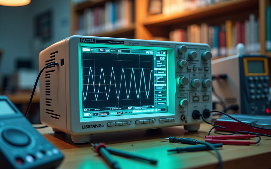
Alternatively, oscilloscopes provide a robust method for visualizing waveforms. By displaying both voltage and current waveforms simultaneously, one can measure the time difference between their peaks. This time difference can be converted into a phase angle using the formula:
Phase Angle (degrees) = ) × 360
where Δt represents the time difference and T is the period of the waveform. This approach not only offers a visual depiction of the relationship between stages but also enhances the depth of analysis, facilitating the identification of discrepancies in system behavior.
Incorporating best practices, such as ensuring proper probe placement and calibrating the equipment, can significantly enhance measurement accuracy. Recent statistics indicate that the use of shift meters in electrical engineering has surged, underscoring their essential role in network analysis. For instance, similar to the 30 community initiatives carried out in Cambodia to mitigate disaster risks, precise measurements of electrical parameters can lead to substantial improvements in performance and reliability.
As Rob Landley aptly noted, “people’s light bulbs start exploding” when measurement accuracy is compromised. By mastering these techniques, engineers can leverage the measurement of shifts to optimize circuit performance and resolve complex issues efficiently. Furthermore, case studies on measuring oscillation positions with oscilloscopes illustrate , further emphasizing the significance of these methods in real-world scenarios.
Address Challenges in Phase Angle Measurement and Interpretation
Assessing angular measurements in electrical systems presents significant challenges, notably signal distortion, noise interference, and equipment calibration issues. Signal distortion often arises from non-ideal elements within the system, leading to inaccurate angle readings. To mitigate this, it is essential to ensure that all components are operating optimally and that connections are secure.
Noise interference from nearby electrical devices can severely affect measurements. Utilizing shielded cables and implementing proper grounding techniques are effective strategies to alleviate this concern. Moreover, the calibration of measurement equipment is critical for maintaining accuracy. Regular adjustments of measurement devices and oscilloscopes, in accordance with the manufacturer’s guidelines, are vital for ensuring precise readings.
Analyzing results necessitates a contextual understanding of the system. For instance, a rotational measurement that appears excessive in one context may be appropriate in another. Engineers must consider the specific requirements of their circuits when interpreting data related to timing shifts.
Recent studies underscore that noise interference can lead to substantial inaccuracies in measurements, with some reports indicating that up to 30% of readings may be affected by . Furthermore, advancements in technology, such as the development of compact MIMO architectures, illustrate the potential for enhanced performance in environments characterized by high spatial interference, particularly relevant for applications like 5G communication. For example, MIT researchers have developed a new millimeter-wave MIMO wireless receiver architecture designed to effectively manage stronger spatial interference, capable of blocking up to four times more interference than similar devices. This compact architecture, built on a 3.2-square-millimeter chip, exemplifies how technology can improve measurement accuracy in challenging environments.
Negar Reiskarimianian, a Career Development Assistant Professor in the Department of Electrical Engineering and Computer Science, highlights the necessity of addressing interference: “If you start getting disconnected or your signal quality declines, you can activate this feature to mitigate that interference on the fly. Our parallel approach allows you to toggle it on and off with minimal impact on the performance of the receiver itself.” By recognizing these challenges and employing effective mitigation strategies, engineers can significantly enhance the reliability of their phase angle measurements.
Conclusion
The exploration of phase angles in electrical engineering underscores their vital role in the analysis and optimization of alternating current (AC) systems. By quantifying the phase difference between voltage and current waveforms, engineers gain critical insights into circuit behavior, power factor efficiency, and the performance of reactive components. The relationship between phase angles and circuit design is paramount, directly impacting component selection and the overall efficiency of electrical systems.
Accurate measurement of phase angles is essential for effective circuit analysis. Utilizing specialized equipment such as phase angle meters and oscilloscopes enables engineers to visualize and quantify phase relationships, ensuring precise interpretations of circuit dynamics. Despite challenges posed by signal distortion, noise interference, and equipment calibration, employing best practices and advanced technologies significantly enhances measurement accuracy.
In conclusion, mastering the intricacies of phase angles is crucial for engineers seeking to optimize electrical systems. By addressing measurement challenges and leveraging advanced analytical techniques, engineers can improve circuit reliability and efficiency. As the field of electrical engineering continues to evolve, a firm understanding of phase angles will remain a cornerstone in the pursuit of innovative and high-performing electrical solutions.
Frequently Asked Questions
What is timing measurement in electrical engineering?
Timing measurement quantifies the difference in phase angles between two sinusoidal waveforms, typically voltage and current, and is expressed in degrees or radians.
What does a positive phase angle indicate in an AC system?
A positive phase angle indicates that the voltage waveform reaches its peak before the current, signifying a leading position.
What does a negative phase angle signify in an AC system?
A negative phase angle indicates that the current peaks before the voltage, illustrating lagging phase angles.
Why are phase angles important in AC configurations?
Phase angles are important because they demonstrate the relationship between voltage and current in the system, which is crucial for analyzing electrical behavior, especially in reactive elements like inductors and capacitors.
What is the power triangle in electrical engineering?
The power triangle visually represents the interaction among power factor, active power, and reactive power, highlighting the importance of positional relationships in enhancing design efficiency.
What frequency ranges are relevant for AC waveforms?
The frequencies of AC waveforms range from zero (in the case of DC) to kilohertz (kHz) and megahertz (MHz).
Why is understanding resistance and reactance important?
A comprehensive understanding of resistance and reactance is vital for effective electrical system design and analysis, as these elements profoundly impact AC performance.
How does the direction of electrical flow influence phase angles in an AC system?
The direction of electrical flow in an AC system alternates periodically, which influences the dynamics of phase angles.